|
Consider a case where the perfs are at 90 degree phasing, and just happen to line up with the principle horizontal stress. When the borehole is pressurized until breakdown, in Case 1 the breakdown occurs at A, and you are able to put in a classic single lobed fracture so beloved of the service companies. Immediately after cleanup this well produces the oil adjacent to the fracture surfaces, and then at a declining rate, oil from the formation around the fracture. What you don’t get, and can never get from this stimulation is any oil from the other side of the wellbore because if the formation were that permeable you wouldn’t be doing a hydraulic frac job in the first place.
Fig. 1 Overview of the different cases for fracturing |
|
Now then consider the case 2 where due to the perversity of inanimate objects, breakdown occurs at B. When this happens you’re screwed only you don’t know it yet because the fracture moves out radially through the altered stress field that you have created until it finds out that the real stress field is in another direction, and so it promptly turns and goes in that direction. Since you are pumping water, you don’t have a problem putting in your minifrac and doing your diagnostics, but there aint no way that you will ever push a significant amount of slurry around that corner. In fact, you’re doubly screwed because now that it has broken down at B it is almost impossible to put enough pressure down this hole to break it down elsewhere. The best way that you can salvage this frac job is to shoot a string shot at whatever pressure you can get down there, and that will break it down at A and C and give you two low impedance pathways that you can pump. This should make you happy because now you are not only going to get the oil from the fracture at A, but you are going to get the same amount from the one at C that you wouldn’t have produced otherwise.
Let’s go back to Case 1 for a minute. That fracture first broke down at a single perf, and then grew both vertically and horizontally. I’m sure that you have seen pictures of fractures in open holes and perhaps have seen the Sandia “mineback” experiments so you know that fractures don’t go straight. They curve around in every dimension, and it is unlikely that this one grew vertically in an absolutely straight line. What that means is that some of the perfs have a good “straight on” connection with the fracture, some have only a grazing connection, and some don’t connect at all. This is a variable that you have no control over, and it probably is different for every job. Let me exaggerate a tad to make a point, and assert that in an extreme case you might be trying to pump 50 tons of sand through half a dozen quarter inch holes. Back to Case 3 now. Here you are guaranteed that over the length of the string shot every perforation has a good “straight on” connection with a fracture, and, keeping in mind that the only fractures that you can pump are the ones that connect to perforations and that go in the general direction of the principal horizontal stress, there is no law that says that you can’t shoot as many string shots as you want in that hole.
If you think about the case where the perfs are phased at 60 degrees or are not aligned with the principle horizontal stress, it’s easy to see cases where two or three fractures from each side of the wellbore could be generated thus greatly increasing communication with the formation and confounding the modelers.
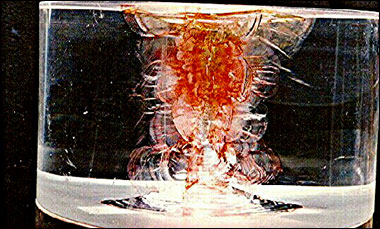
Fig. 2 Shock-Induced-Hydrolically-Driven Fractures in Lucite. The extensive fracture system at bottom was created with 0.00 grams of PETN. All others used 0.008 grams. Internal pressure fro all shots was 1500-2000 psi.
|